Description
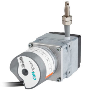
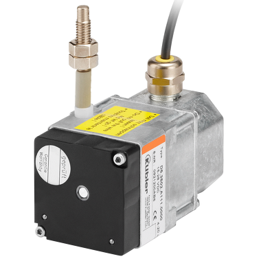
Draw-wire mechanism with analog sensor.
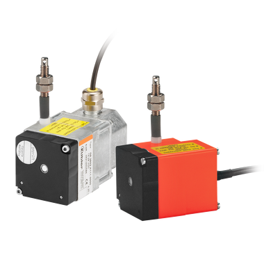
The draw-wire encoders A40 and A41 with analog output is characterized by its compact design. They are available with a potentiometer, voltage or current output.
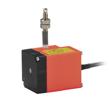
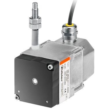
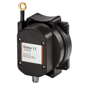
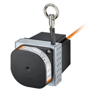
Draw-wire mechanism with analog sensor.
The draw-wire encoders A40 and A41 with analog output is characterized by its compact design. They are available with a potentiometer, voltage or current output.
| Mechanical | |
|---|---|
| Measuring system | Draw-wire encoders |
| Measuring length | 1 m 2 m |
| Speed | 1 m/s |
| Dimension | 50 mm x 50 mm x 77 mm |
| Connection types | Axial cable M12 connector |
| Working temperature | 0 °C … +50 °C |
| Protection level | IP50 IP65 |
| Electrical | |
|---|---|
| max. linearity | ±0,35 % |
| Interfaces | Analog 0…10 V Analog 4–20 mA Potentiometer output |
| Power supply | 15…28 V DC |
Compact and simple
| Data sheet | |
|---|---|
|
A40 / A41 PDF ∼ 614,8 KB | 02.2023 |
Download |
| Declaration of conformity | |
|---|---|
|
A30 / A40 / A41 / B75 / C105 CE Multilingual: German, English, French |
Download |
| Operation Manual | |
|---|---|
|
A40 / A41 Multilingual: German, English, English (USA), French |
Download |
| Mechanical CAD / STEP | |
|---|---|
|
A40 ZIP ∼ 103,8 KB | 05.2019 |
Download |
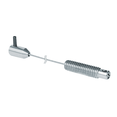 |
Extension cable Paraleine With extension cables, the actual measuring range can be used without any loss of resolution. We offer numerous extension cables in our portfolio for this purpose.
|
||
|
Extension cable steel With extension cables, the actual measuring range can be used without any loss of resolution. We offer numerous extension cables in our portfolio for this purpose.
2 m 8.0000.7000.0033 |
||
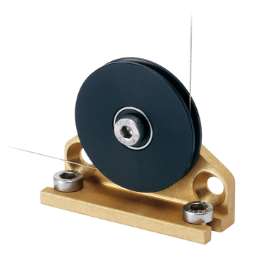 |
Guide pulley With guide pulleys, linear movements can also be directed around obstacles. This not only increases their flexibility but can also compensate for installation tolerances. Idler pulleys can also act to clean off dirt and break ice. Technical data:
Scope of delivery:
8.0000.7000.0045 |
Mechanical CAD / STEP 8.0000.7000.0045 |
Download |
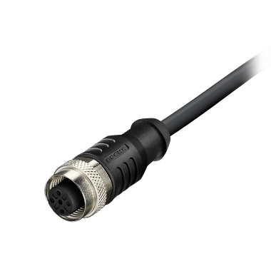 |
M12 Connector with cable , Preassembled cable set
|
Female connector 4-pin PUR Ø 4,7 mm ± mm 4×0,34 mm2 |
05.00.6061.6211.XXXX
|
Data sheet M12 cordset, PUR, socket, 4-pin, A-coded, open end |
Download |
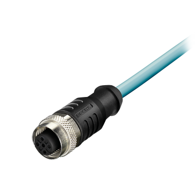 |
M12 Connector with cable , Preassembled cable set
|
Female connector 5-pin PVC Ø 5,5 mm ± 0,2 mm 5 x 0,25 mm2 |
05.00.6081.2211.XXXM
|
Data sheet M12 cordset, PVC, socket, 5-pin, A-coded, open end |
Download |
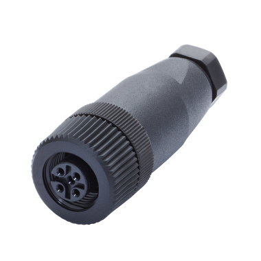 |
M12 Connector , Field-wireable connector
|
Female connector 4-pin |
05.B8141-0
|
Data sheet M12 socket, 4-pin, A-coded |
Download |
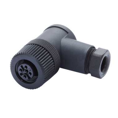 |
M12 Connector , Field-wireable connector
|
Female connector 4-pin |
05.B8241-0
|
Data sheet M12 socket, angled, 4-pin, A-coded |
Download |
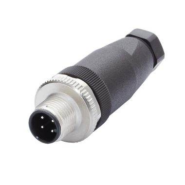 |
M12 Connector , Field-wireable connector
|
Male connector 4-pin |
05.BS8141-0
|
Data sheet M12 pin, 4-pin, A-coded |
Download |