D120

  • Thick V4A measuring cable up to 1.5 mm
  • High protection up to IP69k
  • Different housing types
  • Redundant sensors
  • Max. measuring length 10 m
  • Speed : 3 m/s
  • max. linearity : ±0,1 %

Description

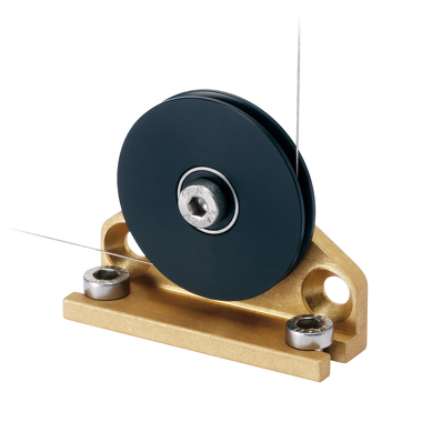
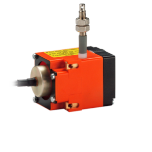
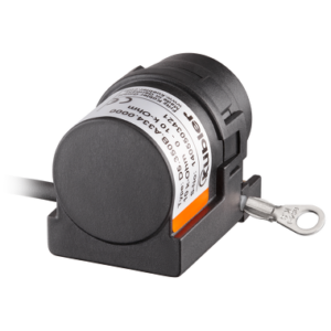
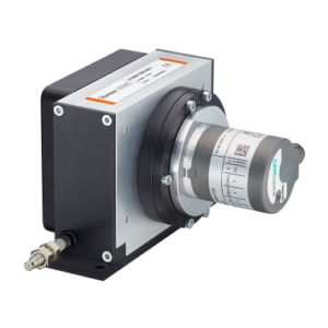
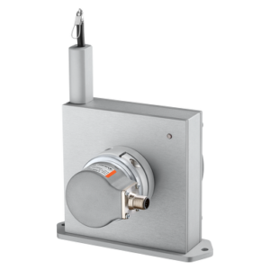
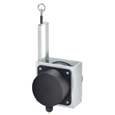
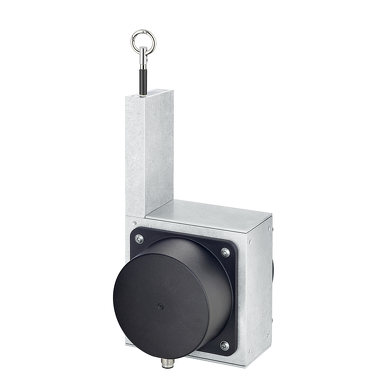
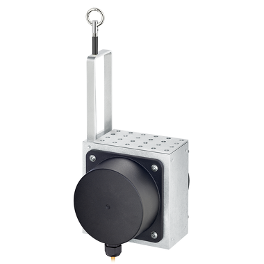
Draw wire encoder – suitable for the harshest environments.

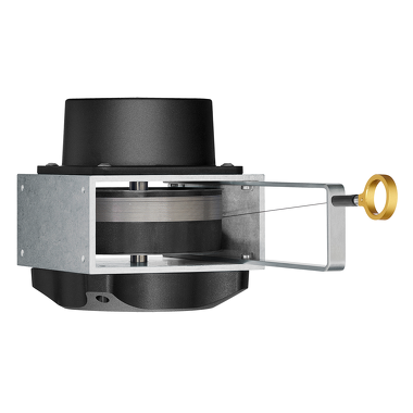
With their extremely robust construction, their high IP69k protection level and their wide temperature range up to -40 °C … +85 °C the D120 draw-wire encoders are specially developed for outdoor applications.

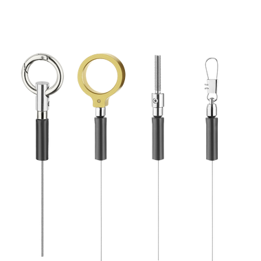
Their flexibility and adaptability reflects in the wide range of housing and wire types, the long measuring range and the various interfaces. The possibility of redundancy must be particularly pointed out.

Technical Data

Mechanical
Measuring system Draw-wire encoders
Measuring length 3 m
4 m
5 m
6 m
7 m
8 m
9 m
10 m
Speed 3 m/s
Dimension 120 mm x 120 mm x 133 mm
Connection types Radial cable
M12 connector radial
Working temperature -40 °C … +85 °C
Protection level IP67
IP69k
Weight 1,60 kg
Electrical
max. linearity ±0,1 %
Interfaces Analog 0…10 V
Analog 4–20 mA
CANopen
Potentiometer output
Power supply 8…30 V DC
12…30 V DC

Benefits

Robust

  • Protection level up to IP69k and wide temperature range up to -40 °C … +85 °C.
  • The titanium-anodized aluminum housing and the stainless steel wires allow using the mechanics even in harsh conditions.
  • Wire diameter (stainless steel, V4A) up to ø 1.5 mm – ideal for outdoor applications.


Versatile

  • Measuring length up to 10 m.
  • Redundant outputs (mA, V, R, CANopen).
  • The right measuring wire and the right wire fastening for every application.
  • Linearity up to ±0.1 % of the measuring range.
  • Various constructions: open, closed housing or housing with perforated sheet steel cover.

Downloads

Data sheet

D120

PDF ∼ 1,6 MB | 04.2023

Download
Declaration of conformity

C60 / D120 CE

Multilingual: German, English, French
PDF ∼ 347,9 KB | 07.2018

Download
Installation manual

Safety Advice for Draw-wire encoders

Multilingual: German, English, French, Italian
PDF ∼ 160,6 KB | 05.2017

Download
Device file

C60 / D120

ZIP ∼ 2,6 KB | 04.2019

Download
Manual

C60 / D120

PDF ∼ 389,3 KB | 05.2018

Download

D120

PDF ∼ 382,3 KB | 08.2017

Download
Mechanical CAD / STEP

D120

ZIP ∼ 11,5 MB | 03.2018

Download
Safety characteristics

D120 MTTFd

Multilingual: German, English
PDF ∼ 186,3 KB | 06.2019

Download
Flyer

Portfolio overview Draw-wire encoders

Multilingual: German, English
PDF ∼ 221,1 KB | 11.2019

Download

Brochures

Solutions for Mobile Automation

PDF ∼ 6,7 MB | 02.2023

Download

Accessories

Guide pulley

With guide pulleys, linear movements can also be directed around obstacles. This not only increases their flexibility but can also compensate for installation tolerances. Idler pulleys can also act to clean off dirt and break ice.

Technical data:

  • Installation angle (anodized aluminum)
  • Guide pulley (plastic POM)
  • Ball bearing (Type 696-2R5)

Scope of delivery:

  • 2 x countersunk screws for side fixing
  • 2 x Allen screws for fixing on a flat surface

8.0000.7000.0045

Mechanical CAD / STEP

8.0000.7000.0045

Download

Cables and Connectors

M12 Connector with cable ,

Preassembled cable set


Female connector 8-pin PVC Ø 6,7 mm ± 0,2 mm
8 x 0,25 mm2

05.00.6041.8211.XXXM

Data sheet

M12 cordset, PVC, socket, 8-pin, A-coded, open end

Download

M12 Connector with cable ,

Preassembled cable set

Female connector 5-pin PVC Ø 5,5 mm ± 0,2 mm
5 x 0,25 mm2

05.00.6081.2211.XXXM

Data sheet

M12 cordset, PVC, socket, 5-pin, A-coded, open end

Download

M12 Connector ,

Field-wireable connector

Female connector 4-pin

05.B8141-0

Data sheet

M12 socket, 4-pin, A-coded

Download

M12 Connector ,

Field-wireable connector

Female connector 4-pin

05.B8241-0

Data sheet

M12 socket, angled, 4-pin, A-coded

Download

M12 Connector ,

Field-wireable connector

Female connector 8-pin

05.CMB 8181-0

Data sheet

M12 socket, 8-pin, A-coded

Download