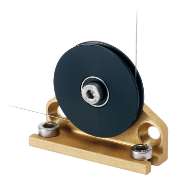
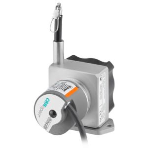
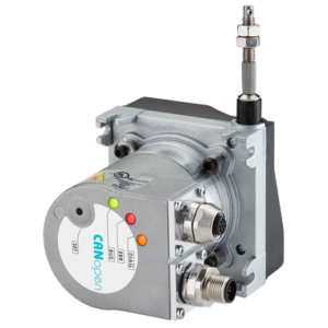
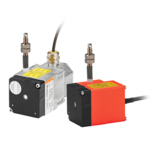
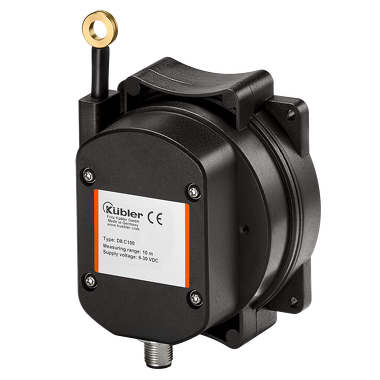
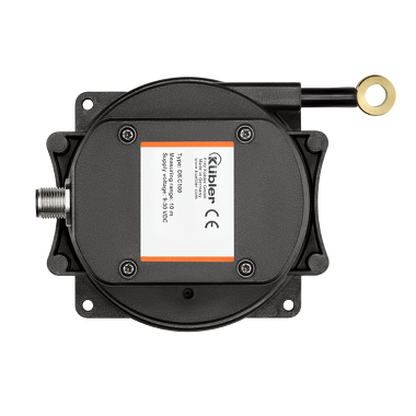
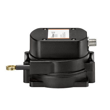
C100

  • Integrated inclinometer
  • Redundant sensors
  • High IP67 protection
  • Max. measuring length : 5 m
  • Speed : 1 m/s
  • max. linearity : ±0,5 %

Description

Draw-wire encoder – economical and innovative.

The draw wire system C100 is more than a sensor for determining length-related position data. Variants with integrated inclinometer and redundant interfaces offer versatile application possibilities.
The contactless magnetic position scanning, a high IP67 protection level and the wider temperature range round off the product.

Technical Data

Mechanical
Measuring system Draw-wire encoders
Measuring length 1 m
2 m
3 m
4 m
5 m
Speed 1 m/s
Dimension 108 mm x 98 mm x 68,4 mm
Connection types M12 connector
up to 2m cable radial
Working temperature -40 °C … +85 °C
Protection level IP67
Weight 500 g
Electrical
max. linearity ±0,5 %
Interfaces Analog 0.5–4.5 V
Analog 0…10 V
Analog 4–20 mA
CANopen
1 x Relay
3 Switching Points
Power supply 9…30 V DC
12…30 V DC

Benefits

Characteristics

  • Measuring length up to 5 m.
  • Integrated inclinometer.
  • Redundant sensors.
  • Different types of sensors (analog, incremental, CANopen, relay output, switch output).
  • Linearity up to ±0.1 % of the measuring range.
  • High protection level IP67 and wide temperature range from -40 °C … +85 °C


Advantages

  • The suitable measuring length for every application.
  • Cost, space and installation work saving.
  • For even higher plant availability.
  • Simple selection and fast installation.
  • High accuracy at economic prices.
  • Reliability and long service life for outdoor applications.

Downloads

Data sheet

C100

PDF ∼ 693,9 KB | 02.2023

Download
Declaration of conformity

C100 / D125 CE

Multilingual: German, English, French
PDF ∼ 351,6 KB | 08.2018

Download
Installation manual

C100, Sensor Option SW3 Sensor option SW3

Multilingual: German, English, French, Italian
PDF ∼ 724,2 KB | 06.2017

Download

Safety Advice for Draw-wire encoders

Multilingual: German, English, French, Italian
PDF ∼ 160,6 KB | 05.2017

Download
Safety characteristics

C100 CANopen – MTTFd

Multilingual: German, English
PDF ∼ 239,3 KB | 06.2019

Download

C100 MTTFd

Multilingual: German, English
PDF ∼ 209,7 KB | 06.2019

Download
Manual

C100 / D125

PDF ∼ 1,5 MB | 04.2020

Download
Device file

C100 / D125

ZIP ∼ 2,9 KB | 04.2018

Download
Mechanical CAD / STEP

C100

PZIP ∼ 240,0 KB | 12.2019

Download
Flyer

Portfolio overview Draw-wire encoders

Multilingual: German, English
PDF ∼ 221,1 KB | 11.2019

Download

Accessories

Guide pulley

With guide pulleys, linear movements can also be directed around obstacles. This not only increases their flexibility but can also compensate for installation tolerances. Idler pulleys can also act to clean off dirt and break ice.

Technical data:

  • Installation angle (anodized aluminum)
  • Guide pulley (plastic POM)
  • Ball bearing (Type 696-2R5)

Scope of delivery:

  • 2 x countersunk screws for side fixing
  • 2 x Allen screws for fixing on a flat surface

8.0000.7000.0045

Mechanical CAD / STEP

8.0000.7000.0045

Download

Cables and Connectors

M12 Connector with cable ,

Preassembled cable set


Female connector 5-pin PVC Ø 5,5 mm ± 0,2 mm
5 x 0,25 mm2

05.00.6081.2211.XXXM

Data sheet

M12 cordset, PVC, socket, 5-pin, A-coded, open end

Download

M12 Connector with cable ,

Preassembled cable set

Female connector 12-pin PUR Ø 7,5 mm ± mm
6 x 2 x 0,14 mm2

05.00.60B1.B211.XXXM

Data sheet

M12 cordset, PUR, socket, 12-pin, A-coded, open end

Download

M12 Connector ,

Field-wireable connector

Female connector 5-pin

05.B-8151-0/9

Data sheet

M12 socket, 5-pin

Download

M12 Connector ,

Field-wireable connector

Male connector 5-pin

05.BS-8251-0/9

Data sheet

M12 pin, angled, 5-pin, A-coded

Download

M12 Connector ,

Field-wireable connector

Female connector 12-pin

8.0000.5162.0000

Data sheet

M12 socket, 12-pin, A-coded

Download